For this project, we decided on making some modular origami. At first, it was the terminology that drew me in – last semester, I took a number theory class where we worked closely with modular arithmetic. The modular in modular origami has a slightly different meaning – it refers to how the origami structures are made with multiple similar or identical modules that fit together.
We went into this project with more of the making than the math in mind. We found a website by the name of Origami Heaven which has instructions for a good selection of modular origami designs. From there, we chose designs that we were interested in, and started folding.
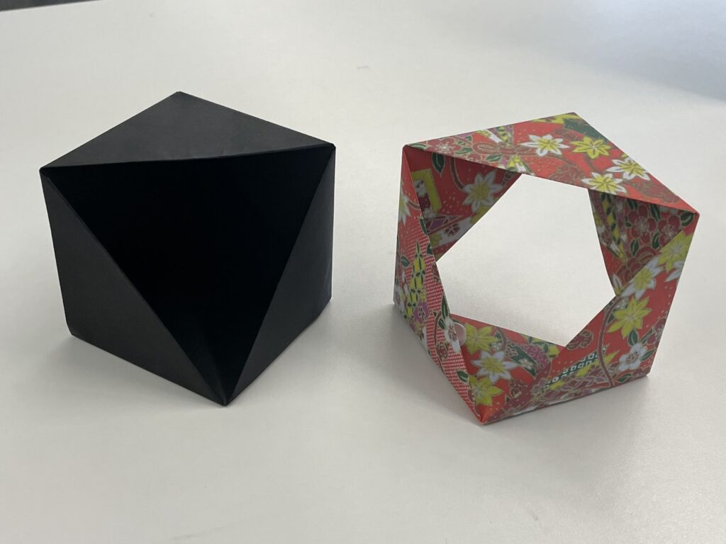
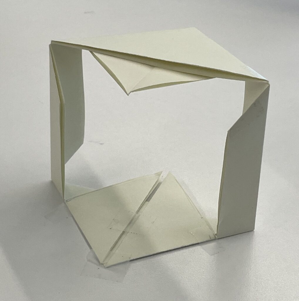
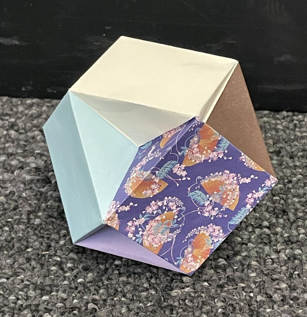
For me, the mathematical significance of what I was folding only really became clear once I had finished the process. I had decided on folding a half-cube, a three quarters-cube (both here) and a Columbus cube.
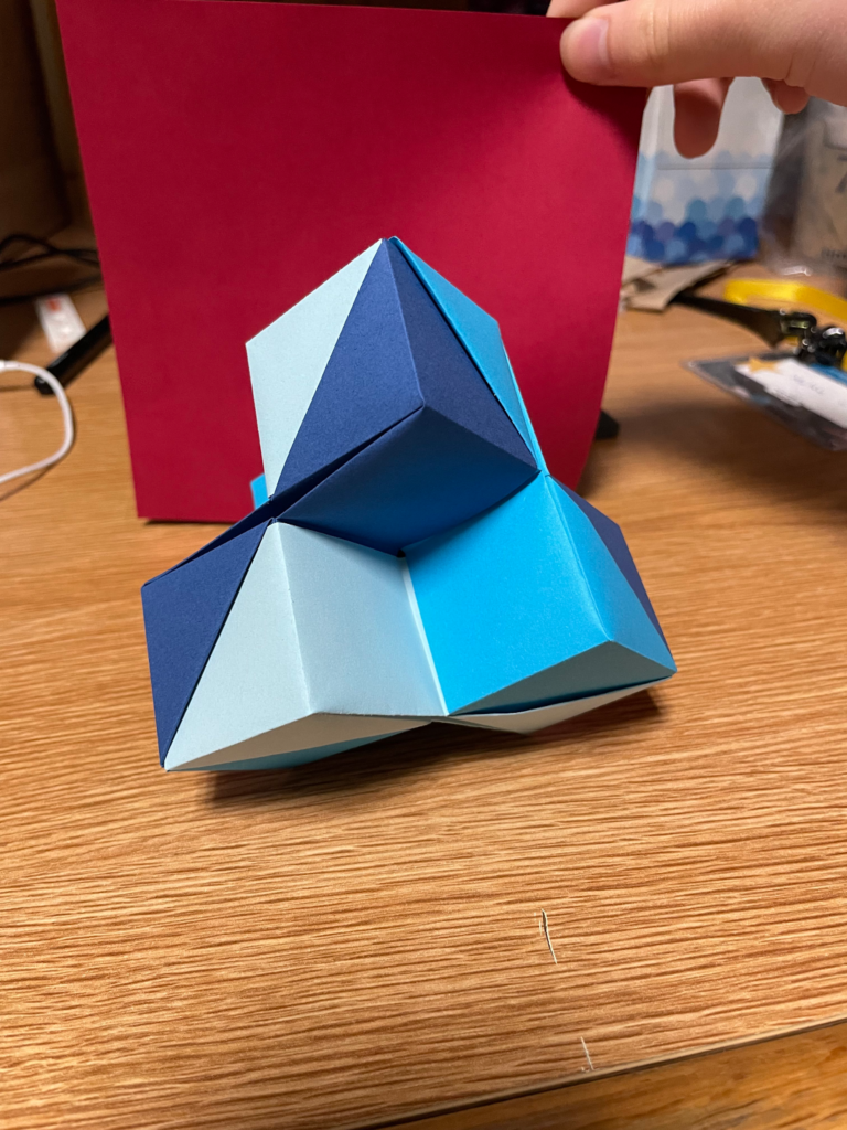
When discussing possible mathematical connections to these that I had folded, Prof. Kagey pointed out that the half-cube had a similar silhouette to that of a Prince Rupert’s cube. The left image below is a 3d model of a Prince Rupert’s Cube, and the right image below is an origami three-quarters cube and an origami half-cube.
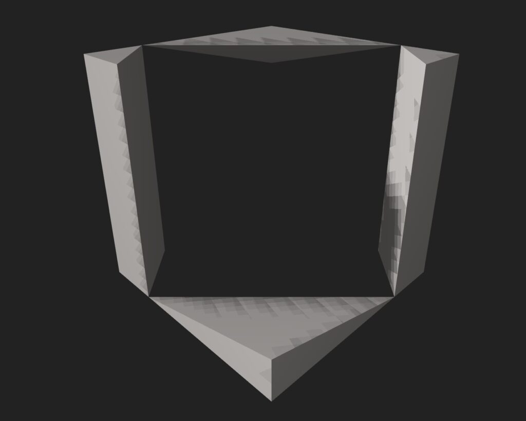
A Prince Rupert’s cube is a cube that has been cut in a way such that another cube can pass through it. This got me thinking- could one fold a Prince Rupert’s cube from origami? From what I found, most likely not. At the very least, it doesn’t seem that anyone’s done it before. However, comparing the half-cube and Prince Rupert’s cube, it seems that it would be possible to cut an origami half-cube such that it would perform the same as a Prince Rupert’s cube. Like so!

The cuts on an origami half-cube to make it a Prince Rupert’s cube are likely much simpler than those on a solid cube, too. Due to paper being flat, one wouldn’t have to worry about excess material on the top and bottom planes that would prevent a cube from passing through. (I really don’t know how to phrase this- Prince Rupert’s cube has a slant at the top and the bottom, so that a cube kinda passes through diagonally. You wouldn’t have to worry about that with paper.) Cool!
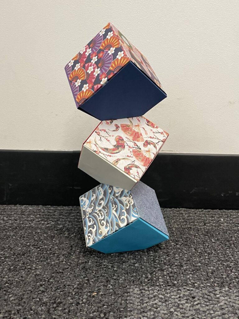
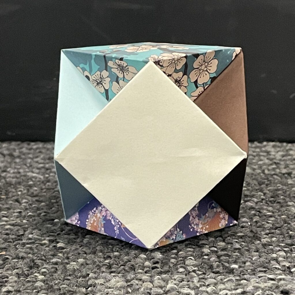
Columbus cubes are very similar to normal origami cubes, with a twist- one corner is inverted, such that the cubes can be stacked on top of each other on their corners rather than their faces.
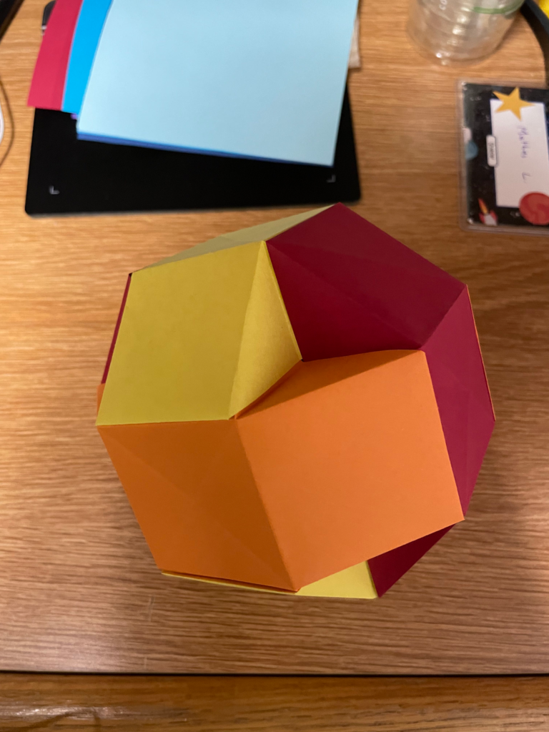
Again, an idea was proposed to me- what if I inverted all corners on a Columbus cube? What would that look like? The answer, it turns out, is that it looks like a cuboctahedron, but where the triangular faces are instead inverted corners.
This is due to a process known as rectification, also known as “complete-truncation”. Where a typical truncation only cuts a bit of the corner off, rectification finds the midpoint of each edge and makes the cuts through there, such that you remove the maximum amount of material. Columbus cubes, to make the folds easier and the cubes stack more nicely, have you fold the inverted corners at the midpoints of the sides. So, by inverting all corners of a Columbus cube, I was inadvertently creating something akin to a cuboctahedron. Neat!
I have had some experience with modular origami in the past, and was interested in the mathematics behind the coloring of modules. When making a build, I aim to maintain some sort of rotational symmetry, ensure adjacent modules have different colors, and use the minimum number of colors. For instance, the “best” way to color a cube is to have three pairs of colors on opposite sides. Below is a four cubes structure that I used six pieces of paper, two of each color, and a cuboctahedron with the same paper configuration. The one on the right had a note that the assembly process was quite difficult and not meant for beginners. The locking mechanism involves a two layer mesh, and when unsecured, the pieces took up a lot more space than the secured version, making assembly more awkward than usual. Furthermore, figuring out exactly how to insert each piece took quite a bit of brainpower and a lot of rotating the object to match the orientation in the directions. In the end, it was very well worth it!
As for the question of how to select the colors of each piece, we can turn to graph coloring! Notably, the Four Color Theorem states that any planar graph can be colored using four colors. However, in three dimensions, there is no equivalent theorem. Furthermore, the additional requirement of symmetry increases the minimum number of colors. Fortunately, we don’t need a general answer when given a specific model! A basic upper bound is the number of pieces in the model, though we can hopefully do better than that.
Here are the minimal colorings of the platonic solids. We can see that there are at most four colors required for any of those, and that there exists rotational symmetry between the colorings: it is possible to “permute” the colors by rotating the solid. As for figuring out how to color the models I folded, I resorted to brute force via trial and error. For both of these, I know that three is the minimum number of colors given that there are three mutually touching pieces. Of course, sometimes I may want to use more colors than the absolute minimum, such as using five instead of three colors for an icosahedron-like Sonobe module. Origami is, after all, an art!
Leave a Reply